Rook Console Hardware!
My Vision
2/19/23
I've been working on the Rook Console on and off for over two years now. It started as a proof of concept laid out on a breadboard and molded into a bunch of individual PCBs jerry-rigged into a jank casing. While my current design "works" in a sense, it's a mess and it has lots of issues. Therefore, I've decided to develop a mainboard for my console. There are many different pros and cons to this decision. Designing a PCB is a challenging task and is something that I have no experience doing. Another con is that it will be a lot more expensive compared to buying cheaper boards that I can easily find on amazon. However, I am going to design my own mainboard, as the benefits outway the cons. While I have no experience designing PCBs, I hope to log my journey as a guide to other developers and hobbyists to help others understand the process. It's certainly a valuable skill and one that I hope to learn through this process. While my final product will be more expensive than buying random premade boards and frankensteining them together, I will be able to make a more compact and reliable console. Soldering a bunch of wires together and trying to shove it all into a small casing is very difficult and so far I haven't done the best job of doing it correctly. My goal is to create a design that makes replicating my build process similar, for both the casing and the hardware. Let's get to it! :D
What do it need?
2/19/23
First off, I need to figure out what all my board needs to have on it. Hmm, maybe some sort of list would be helpful here.
- ESP32 module of some sort
- USB to UART chip
- USB C port
- Power delivery circuit of some sort
- Battery hookup
- Battery protection circuit
- DAC for audio
- SD card reader
- Display hookup
- Power button connector
- Four buttons
- Joystick
- Some way to connect to the main board
PCB Development
2/19/23
Weeee. I think I've learned how to make pcbs now. I followed this tutorial video. Massive
props to the guy who made it, it was very easy to follow and really helped me understand
the design process and the software. I didn't fully go through his tutorial but I do
better understand how to use the software now and will be referring back to it for my
implimentation of the ESP32 into my board. I'm using EasyEDA and will most likely use
JCLPCB to manufacture the board. Here are some screenshots of my crappy unfinished dev
board following his tutorial lol, it taught me how to use the software therefore I
believe I'm ready to give my own board a crack.
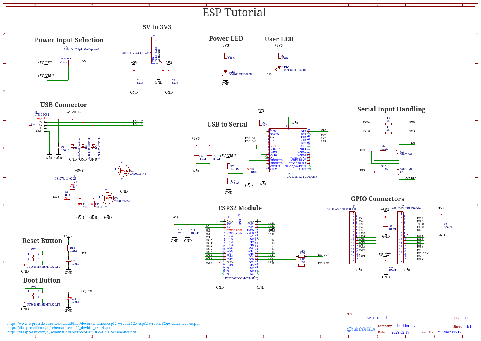
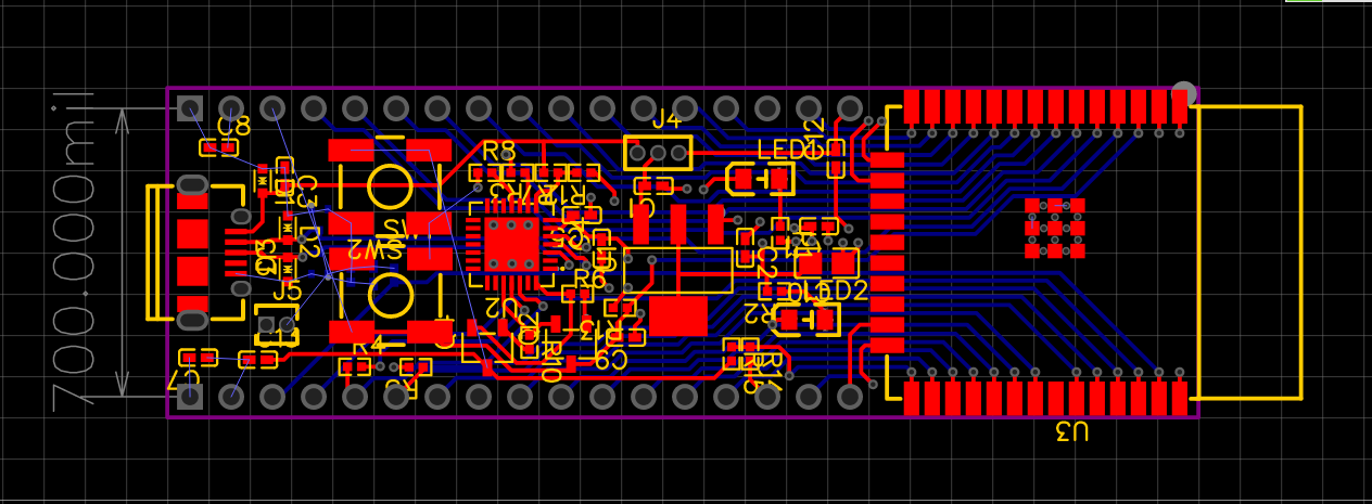
 Yes i know i didn't fully finish it. I learned how to use the tool, which was my goal. Hehehe, custom board here i come >:D
ESP Module >:(
2/19/23
There are sooooo many different ESP32 SoCs to choose from when working on a project like this. Do I want a lot of flash? I do want a lot of PSRAM? Maybe I only want a single core board. Maybe I want a dual core board. Maybe I want a PCB antenna attached to the SoC. Maybe I want to use an external antenna. There's so many different variations of the ESP32. There's even different cores depending on the refresh and make of the board. How on the earth will I ever choose which one to use? Well, let's start with looking at the different series of ESP32s. They are as follow:
Yikes, thats a lot of different lines to choose from o.0 Well, lets start with something simple. I know that I want to have a dual core SoC, so lets knock out any line that only has a single core. The ESP32-S2 series only has a single 240 MHz core, therefore it isn't going to be helpful for my purposes. The ESP32-C2 series has a single RISC-V based 120 MHz core, therefore it isn't going to be an option either. The ESP32-C3 line has a slightly faster 160 MHz RISC-V based core, however it has only a single core. The ESP32-C6 has only a single core, therefore it also isn't suitable for my needs. The ESP32-H2 series has a lower power 96 MHz core, which also isn't going to be helpful. That leaves me with the ESP32 and the ESP32-S3 lines. The ESP32 series is the original line of the chips. They have both single and dual core configurations, and support 2.4 GHz Wifi and Bluetooth Classic/Bluetooth LE. The ESP32-S3 is a Xtensa LX7 dual core processor that runs at 240 MHz, and has 2.4 GHz Wifi as mes on. I've considered having a game interpreter that runs images of games through the microcontroller to allow for more games to be stored on external storage, however I am undecided as to how I want to impliment that as of now. So the more flash and RAM available the better. This leaves me with the ESP32-S3 series to work with, which is a much smaller list of possible modules to choose from. They are as follow: Well hey! Thats not too bad at all. There's only a few options left to choose from. The ESP32-S3-WROOM-1/1U is the best documented of the modules. There's several dev boards based upon this design that I could use as a basis for my board. It supports up to 16MB of flash and up to 8MB of PSRAM. The ESP32-S3-WROOM-2 is very similar to the previous module, however it has 3 less GPIO pins, and can support up to 32MB of flash and 8MB of PSRAM. However, I was unable to find a board with a schematic that used this module, meaning that I would only have espressif's datasheet to make a board off of. That's not something I really want to do, therefore I'm going to cross it off from the list of options. It's also incredibly expensive, costing over $18 USD, where as the previous model's top spec costs just over $5 USD. The ESP32-S3-MINI-1/1U supports up to 8MB of flash and 2MB of PSRAM in an external package. It has 3 more GPIO pins than the first module. However, it's also getting crossed off of the list, leaving me with only the ESP32-S3-WROOM-1/1U module. The difference between the 1 and the 1U variant is that the 1 variant has a PCB antenna, while the 1U variant has an external antenna connector. For my purposes, I'd like to use a PCB antenna, so I'm going to use the ESP32-S3-WROOM-1 module for my project. But wait! There's more! There's different variants of the individual module. Yuck. So many different things to take into account. However, this choice is quite easy. The last portion to decide is how much flash and PSRAM I want to have on the module. For my use case, I want as much as possible, so I'm going to use the ESP32-S3-WROOM-1-N16R8 module with 16MB of flash and 8MB of PSRAM. Say ESP32-S3-WROOM-1-N16R8 three times fast. You can't >:PImportant Links
ESP-S3-WROOM-1 Datasheet ESP32-S3-WROOM-1-N16R8
Existing ESP32 Dev Boards
2/20/23
Alright. I've decided on what ESP32 module I'm going to use. Now I have to design the rest of the board around it. Just like the video tutorial that I followed to learn how to use EasyEDA, I'm going to be taking a look at some dev boards that already exist in order to choose parts and make my schematic. Here's a list of all the different schematics I found that use the ESP32-S3-WROOM-1(the flash and PSRAM doesn't matter in this case because the pinout will stay the same.):
- ESP32_s3_box_v2.5
- ESP32-S3-EYE-MB
- ESP32-S3-Korvo-1_V6
- ESP32-S3-DevKitC-1
- funny schematics that may or may not be useful
- wrong SoC but interesting battery circuit
- goofy battery hookup with different uart chip
- power switching circuit? :o
- funny battery psu part
- pretty informative reddit thread
No im not dead
5/5/23
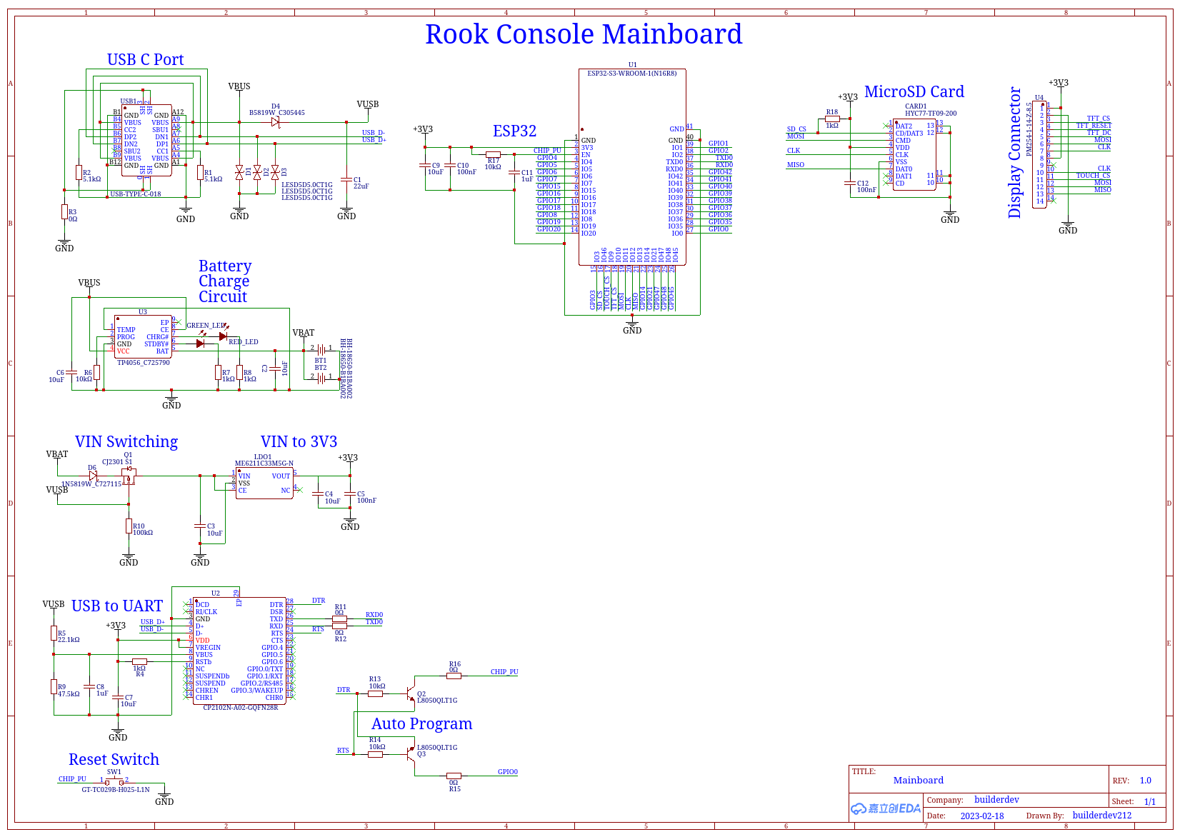
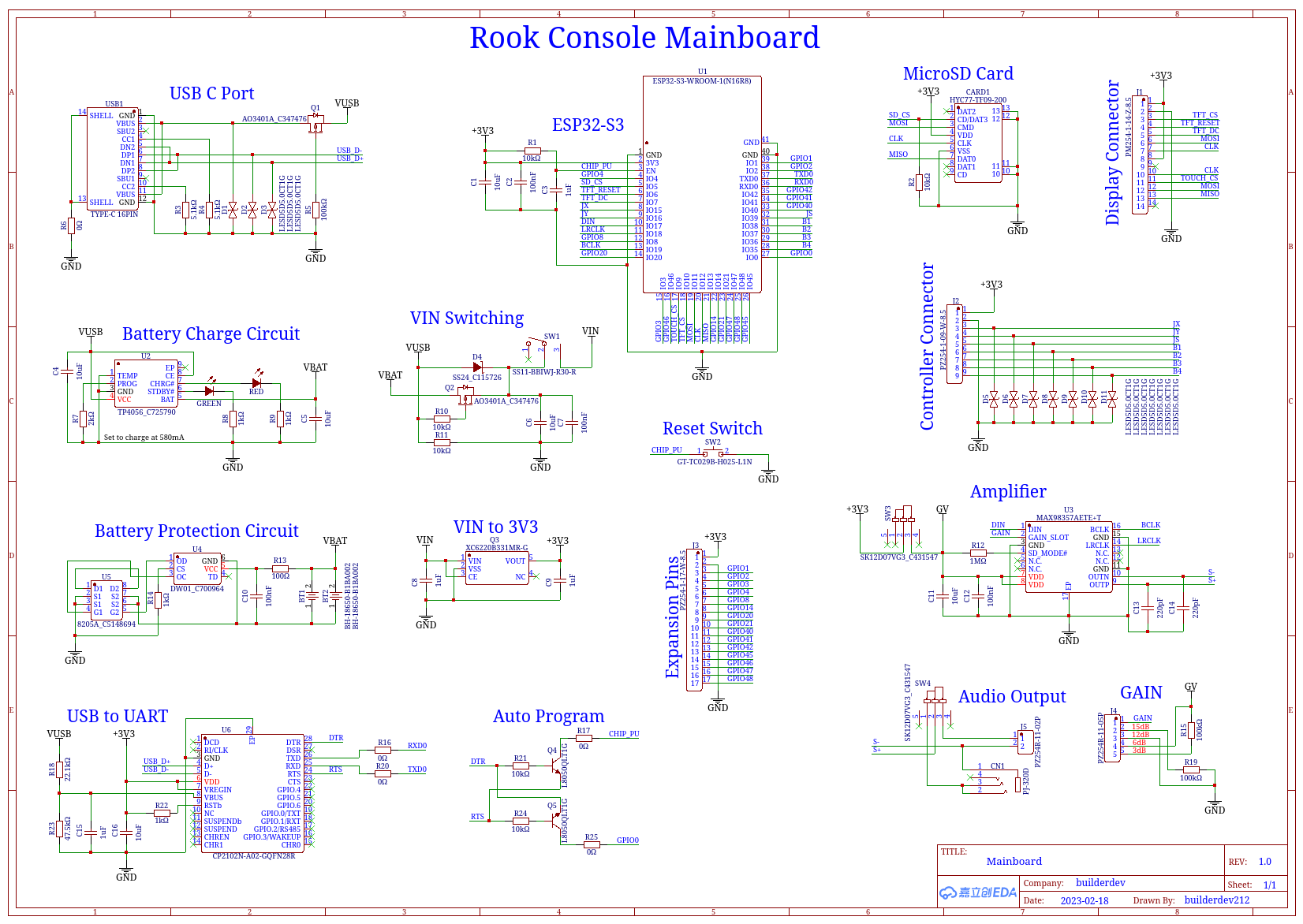
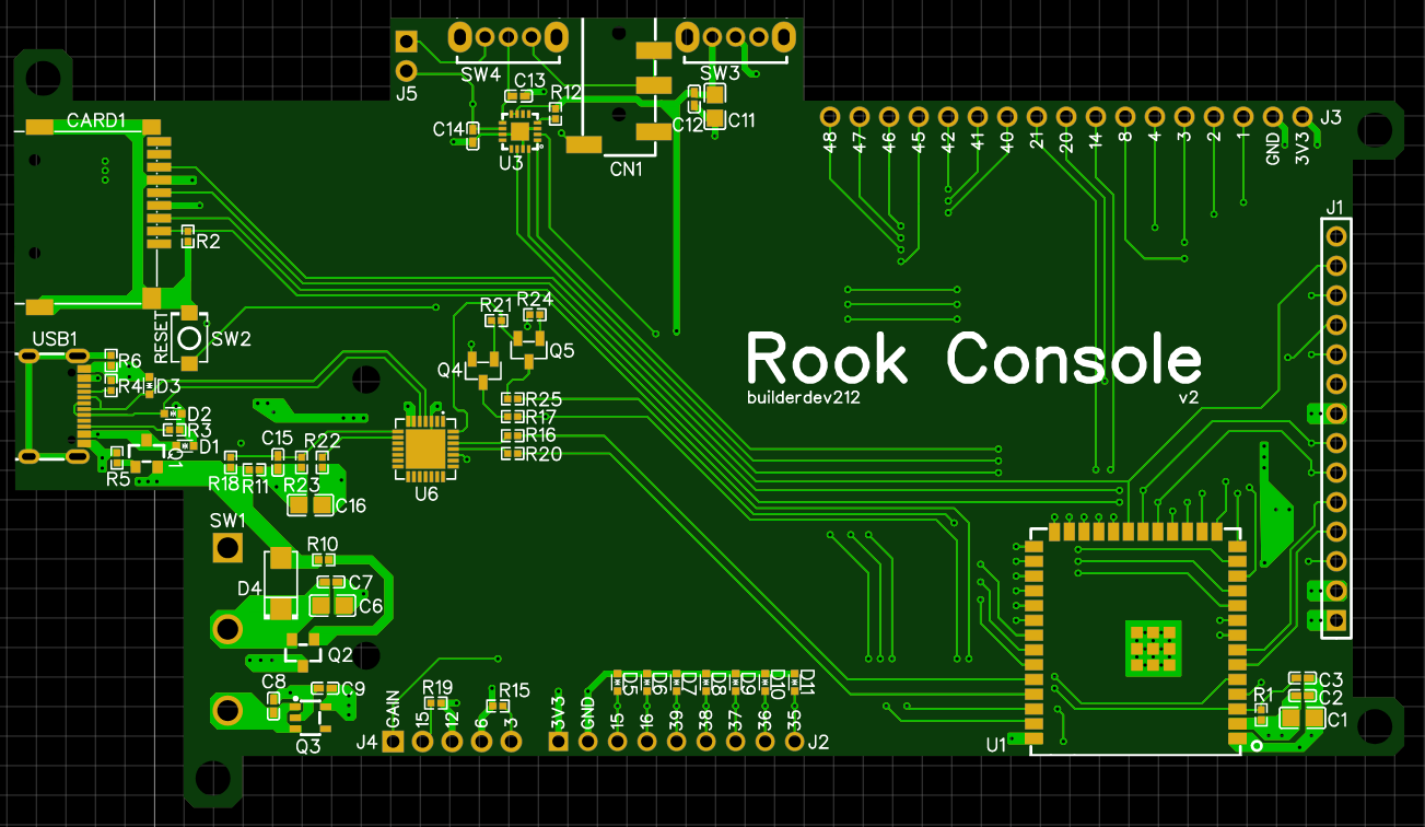
Finished PCB (untested)
5/23/23
I've just ordered my board and will update this again when I test it. A huge
thank you to the folks over on reddit who helped me get this figured out.
see this post for the first schematic review and this post for the second
schematic review. This post is the pcb review itself. Below is my final
design, and I will update this once again when I recieve the board.
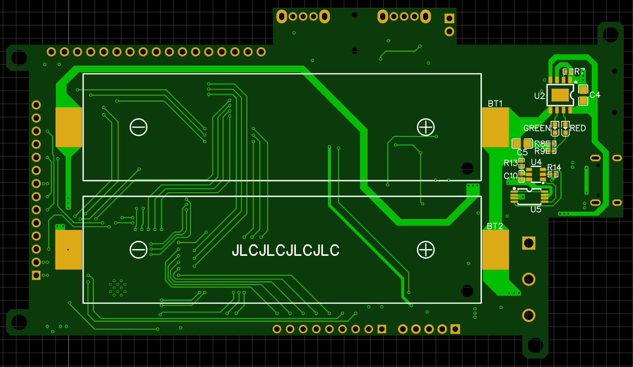
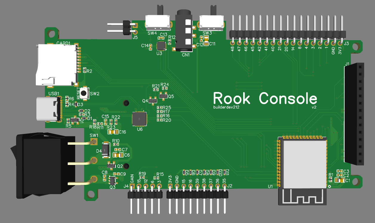
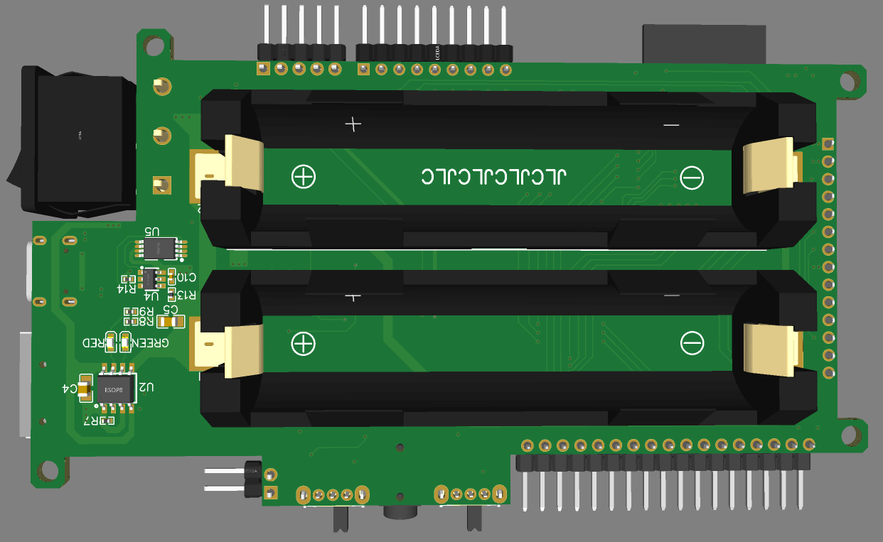
Finished PCB (tested!)
1/22/24
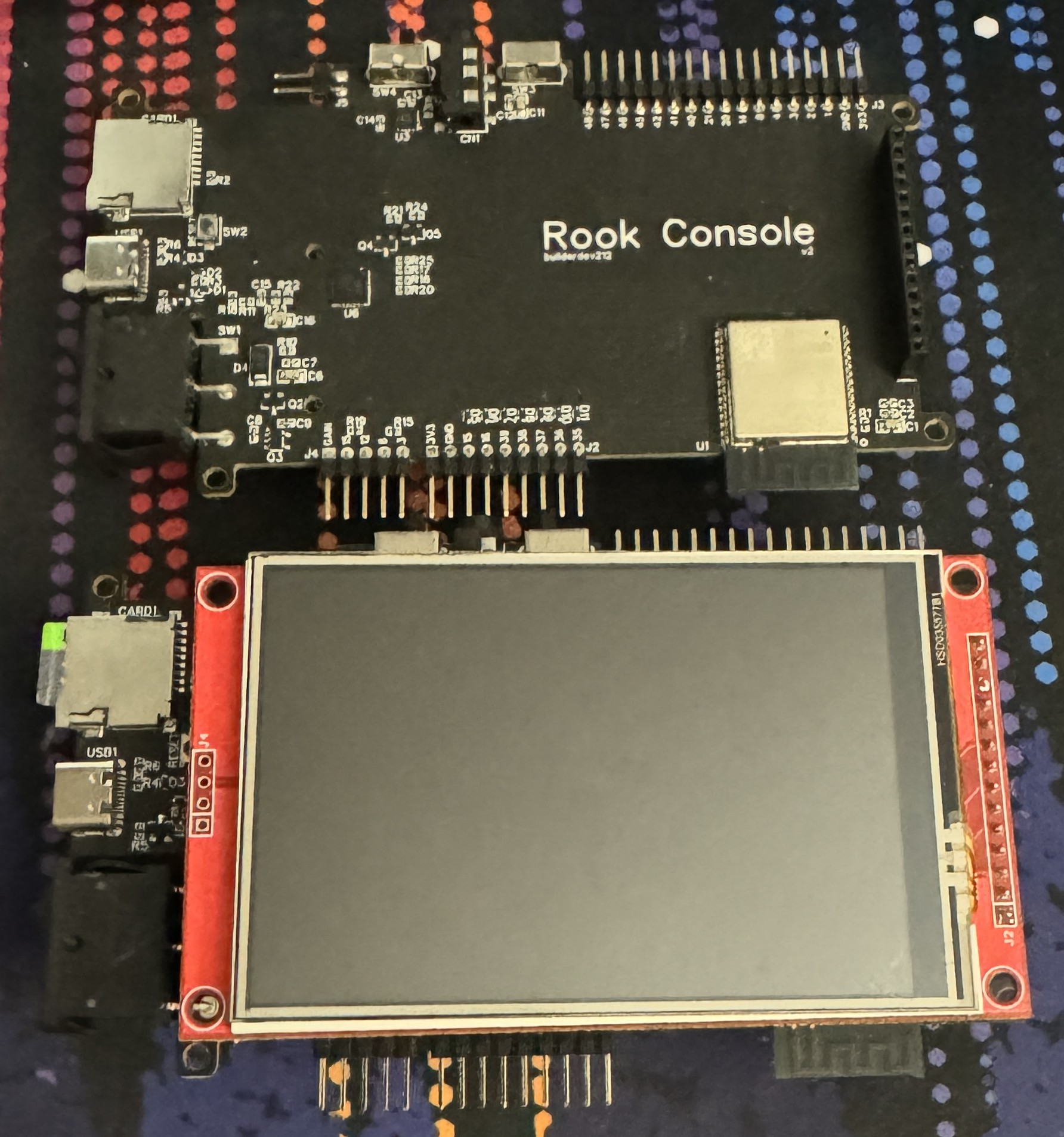
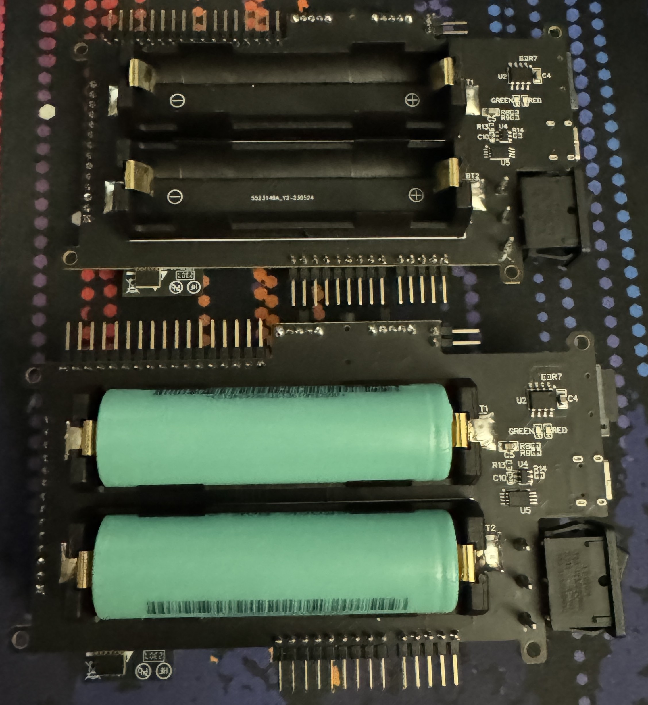
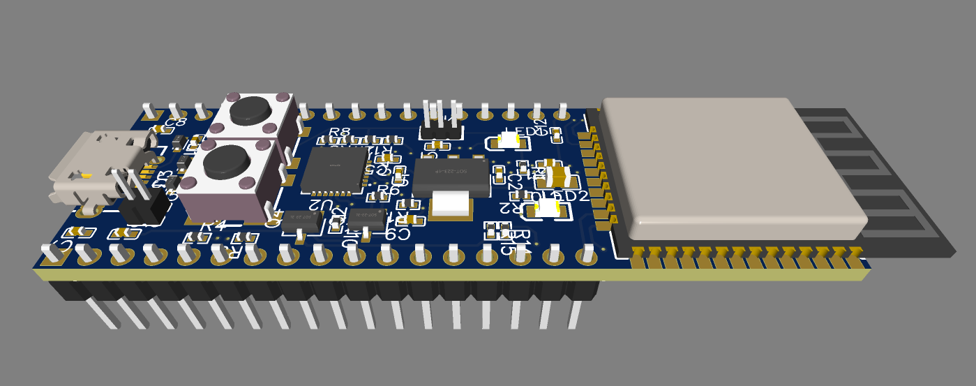
It's been a while since I last updated this devlog. I'm going to call this
"finished" for now. The board does work! Every part of the board works to
my knowledge. However there are some caviats. I managed to flip my rx and
tx on my usb port, however with a custom usb cable this isn't a problem for
my current development. I'm going to split off into a few different devlogs
for different parts of the project code. I'm going to end this off with
pictures of what the current board looks like. My first PCB has been made,
and works.